

Do you want to calculate a gas spring (also know as gas strut) for your application (lid, hatch, folding bed, etc.)? You can easily do this with our calculation tool. You can calculate and order a gas spring in 4 steps. These steps are explained in detail below. You can also watch our instruction video ► to get started or download the explanation in pdf.
Download our paper angle meter here or measure the angle open and angle closed with your smart phone or tablet. To do this, go to gasspringsshop.com/am with your tablet or telephone. Click here to reset the calculation tool.

Step 3 - Details:
Edit the information below to make the solution exactly to your wishes:
Step 4 - Order now:
Explanation gas spring calculation: 4 steps
We have tried to make the calculation tool as user-friendly as possible and continuously try to improve it. The calculation tool is very suitable for normal lids or hatches. The calculation tool can also be used for less standard applications.
Calculate gas spring? How do I calculate a gas spring?
Follow these steps to calculate a gas spring:
- Decide what you want to use the gas spring for.
- Enter the dimensions of the application.
- Measure the thickness of the application.
- Investigate which material the application is made of.
- Determine the total weight of the application.
- Determine the position of the pivot point.
- Choose how many gas springs you want to use.
- Check the angle of the application.
The detailed explanation below can help you successfully make a gas spring calculation for your application.
Step 1: entry of the data
Step 2: the calculation
Step 3: adjustments
Step 4: ordering and assembly
Step 1: entry of the data
In step 1 please enter the following information about the cover:
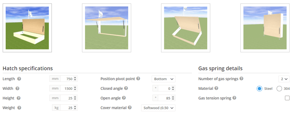
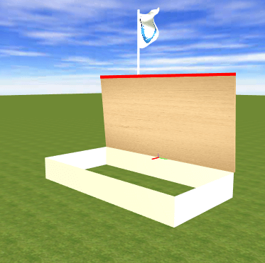
It is important that you enter the requested data as accurately as possible. The calculation tool can then calculate a gas spring as accurately as possible and determine the points where to attach the gas spring. When you click on a question mark you will see a brief explanation of what exactly you must enter. First of all you need to click the image that most closely resembles your application. The first image applies, for example, to a toy box. The second image on a market stall. The third image applies to an angled cover. The fourth image applies, for example, to a horse trailer. For the calculation, pictures 1 and 4 are actually the same. Only the visualisation and simulation then correspond better with your actual application.
Below step 1 you will see the cover appear as you entered it in the simulation. So check the simulation carefully. Then you will immediately see whether you have entered it correctly.
Length [mm / inch]
Closed angle [degrees]
With a normal box, the closed angle is usually 0 degrees (because the cover is then horizontal) and with a market stall -90 degrees (because the cover is vertical when closed). This can of course differ per application. Download our paper angle meter here or measure ⊾ the angle close and angle open with your mobile phone or tablet. To do this, go to gasspringsshop.com/am with your tablet or telephone.
Weight [kg / lb]
Enter the weight of the entire cover here. It is best that you remove the cover and weigh it on the scale. If the cover cannot be detached, you can approximate the weight as follows. Make sure the cover is horizontal and weigh on one side with a scale how much this side weighs. The total weight of the cover then is 2x this weight. Note: this method only works for a simple rectangular cover.
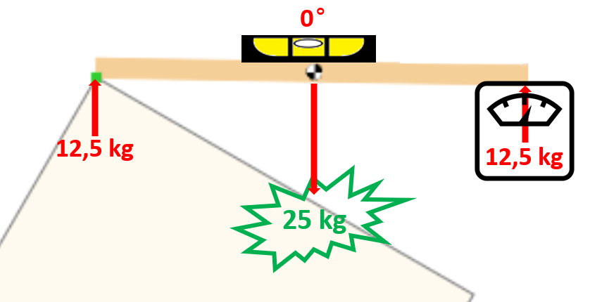
Totale weight [kg] = 2 x 12,5kg = 25kg
Number of gas springs
Select here the number of gas springs that you want to apply. Usually two gas springs are used: one on both sides of the cover. It is also possible to use one gas spring, but then there is a chance that the cover will skew or not close completely close to where the gas spring is located. This will happen less likely in case you place the gas spring in the middle of the cover. Even then it is important that the cover is stiff enough so that the cover will not bend on both sides.
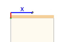
Width [mm / inch]
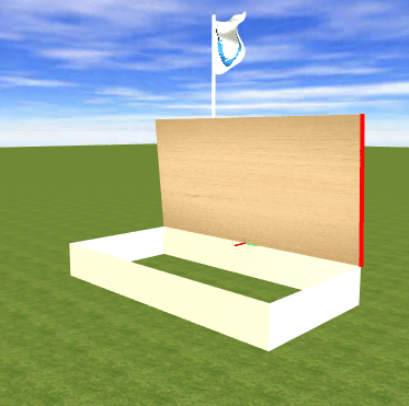
By the width of the cover we mean the side of the cover where the hinges are attached. So do not confuse this with the length of the cover. The red line in the figure below shows the width.
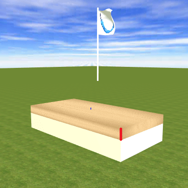
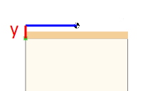
Height [mm / inch]
Enter the height of the cover here. With a cover that only consists of a board, we mean the thickness of the board. If a cover also has edges, you must also take those edges into account. So enter the total height (incl. edges) of the cover. The red line in the figure below shows the height of the cover.
Open angle [degrees]
With a normal box, the open angle is usually 80-90 degrees (because the cover is then vertical) and with a market stall 0 degrees (because the cover is horizontal when opened). This can of course differ per application. Download our paper angle meter here or measure ⊾ the angle close and angle open with your mobile phone or tablet. To do this, go to gasspringsshop.com/am with your tablet or telephone.
Position pivot point
Indicate here where the hinge of the cover is located when the cover is held horizontally (bottom, top, middle or modified). The “modified” option becomes available when you turn on the advanced features. If “modified” is selected, an additional step appears where the position of the hinge can be adjusted manually:
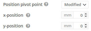
When 100 is entered at the x-position, the hinge will shift 100 mm horizontally away from the cover. When -100 is entered, the hinge will shift 100mm horizontally towards the cover (so the hinge will then be “somewhere” in the cover). When 100 is entered at the y position, the hinge will move 100 mm upwards. If -100mm is entered, the hinge will move down 100mm. The green circle in the simulation shows the position of the hinge. So check carefully whether this is the real position.
Stainless gas spring
If you don’t want to use a stainless steel gas spring, do not check the boxes after 304 and 316. If you tick one of the two boxes, the calculation tool will select the gas springs and the mounting parts of the relevant stainless steel type.
A big difference between stainless steel 304 and stainless steel 316 is in the composition. The weakness of stainless steel 304 is the sensitivity to chlorides and acids, which can result in (local) corrosion. Stainless steel 316 is better resistant to corrosion and environmental influences (eg salt water) due to a different composition. For this reason, stainless steel 316 is often used for aggressive environments.
In addition, the stainless steel 316 gas springs are higher quality. These gas springs have a grease chamber and a built-in clean cap. A grease chamber ensures that the gas spring seal is always properly lubricated, so that it does not matter how the gas springs are positioned. These gas springs can therefore also be mounted with the piston rod upwards or be positioned completely horizontally, without the seal drying out and the gas springs starting to leak. A clean cap ensures that the piston rod is scraped clean, so that no dirt gets into the interior of the gas springs. As a result, the stainless steel 316 gas springs can also be used in the more dirty environments.
Cover material
Enter here what kind of material the cover is made of. On the basis of the specific weight of the material, it is checked whether the total weight of the cover matches the entered dimensions of the cover. If the calculation tool sees that the total weight is too light for these dimensions, the calculation tool will turn the cover into a hollow cover. This means that the height of the cover remains the same, but that the cover has edges and is hollow. This influences the center of gravity of the cover , but also the chosen mounting material and the mounting point on the cover. So check carefully whether the simulation shows the real situation. Only then the calculation tool can calculate the correct gas spring. If you enter “Other” as material, the cover will not become hollow in the calculation tool, but stays solid.
Change center of gravity (advanced)
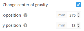
If you check this box, you will see an extra step:
If all data entered in step 1 matches the actual situation, it is better not to check this box. The center of gravity will then be calculated automatically. The center of gravity (black-and-white sphere in the simulation) will be near the center of the cover. Only if the center of gravity of the cover is somewhere else, you can indicate where this should be located in this extra option. Try to determine this as precisely as possible and enter this at this step.
x position
At the x position (in mm) you can enter where the center of gravity is horizontally relative to the pivot point of the cover, if you keep the cover horizontal. With a normal rectangular cover of 750 mm long, the default value will be 375 mm. If, for example, the cover is slightly weighted at the end, you must therefore increase the x position, so that the center of gravity also lies a little more at the end of the cover.
y position
At the y position (in mm) you can enter where the center of gravity is vertically relative to the pivot point of the cover, if you keep the cover horizontal. With a normal rectangular cover of 25 mm long, the default value will be 13 mm (rounded). For example, if something is mounted on top of thecover, you need to increase the y position. Note that the y position is calculated from the point of rotation of the cover and therefore not from the bottom of the cover (which can often coincide if the hinge position is “below”).
Step 2: the calculation
Click on “Calculate” in step 2 if the data entered in step 1 is correct and you have checked the simulation. After the calculation has been performed, you will see the cover with gas spring(s) in the simulation.
There are various buttons above the simulation. If you click on “simulate opening” you will see what happens when the cover is opened. If a hand is visible on the cover, it means that force still needs to be applied by hand. The corresponding force is indicated by the blue arrow next to the hand. The direction of the arrow shows the direction in which that force must be applied. Eventually the hand disappears and the cover will open automatically. If you click on “simulate closing” you will see what happens when you close the cover. The last part the hand will disappear again, which means that the cover will close automatically.
You can also operate the cover with the mouse by clicking on it and holding down the button. You will also see what happens when you raise or lower the cover. The blue arrow always shows which hand force is still needed to keep the cover in this position and in which direction. When you release the cover, it will open, close or remain in the same position. If you click on “Assembly drawing”, you can save and/or print the assembly drawing.
Graph
You now see a 3D image of the cover with gas springs. If you click on “Graph” you will see a graph instead of the 3D image with the forces and moments that play in this application if the cover is held in different angles.
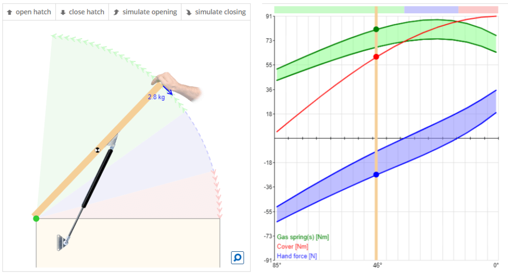
The moment (force times arm measured from the hinge) of the cover in Newton meter (Nm) and the moment (also measured from the hinge measured in Nm) of the gas springs work in the opposite direction, leaving you with a moment in one of the two directions. What you have left is the force (in N) that you still have to use by hand to hold the cover at that certain angle. It is therefore different at every angle in which the cover is held.
Blue arrow with hand force
The hand force can also be seen in the 2D simulation at the blue arrow. If the moment of the cover (the red line) and the moment of the gas springs (the green line) intersect in the graph, no manual force is required (the blue line). There are two green lines. This has to do with the fact that the insertion of a gas spring costs more force than the extension of the gas spring, due to the friction that must then be overcome. A green area therefore appears in the graph. If the red line falls in the green area, the cover will therefore remain in that position.
Because the insertion of the gas springs is heavier than the extension of the gas springs, two blue lines and a blue area will also be created. This is because the manual force will also have to be greater when the gas springs are pushed in (closing the cover) comparing to the sliding out of the gas springs (when the cover is opened).
The example
Let’s take a look at the example above. The cover is held at 46 degrees. A manual force of 2.8 kg is still needed to keep the cover in that position, otherwise the cover will open further automatically. How to read the 2.8 kg from the graph? Given that 1kg = 9.81N. So 2.8 kg is 2.8 x 9.81 = 27.47 N. You can see that in the graph next to the blue circle. You can ignore that in the graph it’s called -27.47N (so negative). It has been decided to call the force negative to close the cover and positive to open the cover. The blue circ;e is on the lower blue line, because the gas spring is inserted and that it is therefore heavier than sliding out.
The cover is 750 mm = 0.75 m long. So in Nm (Newton meter) the hand force at the end of the cover is 27.47N x 0.75m = 20.60Nm. That is also the difference between the green circle (moment of the gas springs in Nm) and the red circle (moment of the cover in Nm). Green is namely at approx. 80 Nm and red at approx. 60 Nm.
Show opened
If you check the box “open hatch”, the simulation shows the position of the cover and the gas spring when the cover is open. The blue arrow at the end of the cover shows the force that you have to press with your hand to close the cover. This is the case if the blue arrow points in the direction of closing (this will normally be the case). If the arrow is in the direction of opening, something is probably wrong. The cover will then not remain open on its own. A hand will also be visible, because then the cover must be supported by hand to prevent it from slamming. The selected gas spring is probably too light for the cover with the selected force. This requires extra attention.
Show closed
If you check the box “close hatch”, the simulation shows the position of the cover and the gas spring when the cover is closed. The blue arrow on the end of the cover now shows the force with which you have to press manually to open the cover. This is the case if the blue arrow points in the direction of opening (this will normally be the case). If the arrow is in the direction of closing, something is probably wrong. The cover will then not remain closed by itself. A hand will then also be visible, because then the cover must be kept closed by hand, so that the cover does not open again automatically. The selected gas spring with the selected force is probably too strong for the cover. This requires extra attention.
Maximum force on pivot point
The simulation specifies the maximum force that will be applied to the hinges of the cover when the gas springs are mounted. By placing gas springs, more is required of the hinges. The force that appears here is an indication of how strong the hinges should be. You may need to install stronger hinges. You can read more information about the force that will be applied to the hinges of the cover and how this can possibly be absorbed here.
Step 3: adjustments
If the simulation already shows exactly what you wanted, then in principle you do not need to change anything and you can accept it for notification. However, in step 3 you can also fine tune the calculation so that it is even more as you wish. There is not just one solution. There are many solutions. If you change something in step 3, you do not have to click on calculate again in step 2. The simulation and the calculation will also change automatically. What information is in step 3 and what can possibly be changed will be explained here.
Type of gas spring
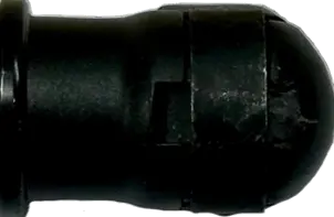
This is the type of gas spring that is selected together with the price. For example, 8-19-200 | € 32.36. The number 8 stands for 8mm diameter rod, the number 19 stands for 19mm housing (the black part of the gas spring) and 200mm stands for the stroke of the gas spring (so the length of the rod that can retract).
If you are going to calculate a gas spring, and the proposed gas spring is quite expensive, you can also select a cheaper gas spring that has more or less the same length as the proposed gas spring. So possibly a gas spring with the same diameter but then a slightly longer or shorter stroke, or a gas spring with a different diameter. The larger the diameter, the more force the gas spring can have. The 4-12 can be up to 200N, the 6-15 can up to 450N, the 8-19 can up to 800N, the 10-23 can up to 1250N and the 14-28 can up to 2500N.
In general it holds that the longer the gas springs (so with a larger stroke) the less force on the hinges of the cover. Often a slightly longer or slightly shorter gas spring will make little difference to the result. You can always check that in the simulation after you have selected the other gas spring. Once you have selected another gas spring, the calculation tool will immediately calculate with this gas spring.
Force gas spring
You cannot see the calculated force here. You can only see this on the order confirmation. You do see a + and a – standing. The calculation tool has calculated a force and with the + and – you can change the force in steps. For the 6-15, 8-19 and 10-23 this is done in steps of 20N, for the 4-12 it is done in steps of 10N and for the 14-18 it is done in steps of 50N. For example, if you like the calculation, but you would like the cover to open a little lighter and close more heavily, you can click on the + once. In the simulation you will immediately see what happens with the different hand forces. So it is often the case: the lighter the cover opens, the heavier the cover closes, and vice versa.
Unused stroke [mm] (advanced)
This is the stroke of the gas spring that will not be used. The minimum unused stroke is 10 mm. There is always room for a little play if the gas springs are not mounted to the mm. Sometimes it may be convenient to increase this distance. This is the case, for example, if the place to mount the gas spring is better. However, the smaller you choose this value, the more you make useful use of the stroke of the gas spring. We therefore advise you to stay close to 10 mm.
Attachment point 1 or 2 in figure (advanced)
With every A measure two points belong to “the fixed world” where the gas spring can be attached. Choose here which suits you best. Please note that some choices are not actually possible because the gas spring and the cover then collide. The calculation tool does not yet take this into account, but it does choose the most likely option.
Rotate buttons (advanced)
At step 3 there are also two rotate buttons. With these buttons you can rotate the gas springs both to the left and to the right. The function of the gas springs will then be exactly the same. The gas springs are rotated in such a way that the hand force remains exactly the same. This can be very useful to mount the gas spring in a different location than shown, while the behavior of the cover remains the same as calculated. An example here is a murphy bed, in which the gas spring is mounted above “the cover”, in this case the bed. With the calculation tool you can calculate a gas spring by rotating the gas spring 180 degrees around the pivot point of the bed in step 3.
Mounting tube side
Select here the mounting parts to be fitted to the tube side of the gas spring. That is therefore the thicker part of the gas spring. This is usually the mounting part that you mount to the cover. The tube must in fact be directed upwards at rest for proper lubrication of the gas spring. Often a bearing shoe is required as an attachment. With a bearing shoe you can mount the gas spring against the bottom of the cover. If the cover has edges at the bottom, you can also choose a side bracket.
Mounting rod side
Select here the mounting parts to be fitted to the (piston) rod of the gas spring. Usually it is the mounting part that you mount to the “fixed world”. A side bracket is often required there. The rod must be turned downwards at rest for proper lubrication of the gas spring.
A measure [mm]
The A measure is the distance from the pivot point to the fixing point of the gas spring on the cover “in length direction of the cover” in mm. Making the A meaure slightly smaller makes it often a little lighter to open and close the cover. However, it is also often desirable for the gas springs to properly close the cover, so that the cover does not open automatically due to the wind or very high temperatures.
B measure [mm]
The B measure is the distance from the pivot point to the gas spring attachment point on the cover “in thickness direction of the cover” in mm. If you use an eye with a bearing shoe, the distance from the bottom of the cover to the pivot point of the gas spring is 20 mm. The calculation tool then shows -20mm as a B measure, but that – can be ignored. This only indicates that the pivot point is “below” the pivot point of the cover. If the B measure is positive, the pivot point of the gas spring is “above” the pivot point of the cover.
C measure [mm]
The C measure is the horizontal distance between the pivot point of the cover and the point of attachment of the gas spring to the “fixed world”. Distance to the center of the eye or ball. You can adjust this measure by checking the box next to “Change C and/or D” and choosing a different position for the C and/or D measure in the 2D figure. When the cursor changes to a ➕ you can click and the gas spring will move to this position. After this, please check carefully if the lid still behaves as desired, because not every position of the gas spring results in good behavior of the application.
D measure [mm]
The D measure is the vertical distance between the pivot point and the point of attachment of the gas spring to the “fixed world”. Distance to the center of the eye or ball. You can adjust this measure by checking the box next to “Change C and/or D” and choosing a different position for the C and/or D measure in the 2D figure. When the cursor changes to a ➕ you can click and the gas spring will move to this position. After this, please check carefully if the lid still behaves as desired, because not every position of the gas spring results in good behavior of the application.
Step 4: ordering and assembly
Do you want to calculate a gas spring and order directly? In step 4 you see the selected gas springs with mounting parts together with the prices. We recommend you to check everything carefully and save or print the assembly drawing directly. You can then click on the shopping cart with the plus sign. The calculated gas springs together with the selected mounting parts will then end up in the shopping cart. After you have checked the contents of the shopping cart, you can place the order.
